FOCUS ON EC FAN ONLY
FOCUS ON EC FAN ONLY
An EC fan can offer precise speed control and efficient part-load operation, but the motor technology does not correct an unsuitable fan type or an incorrect duty point. A fan selected from its maximum airflow alone may fail to deliver the required air after a coil, filter, grille, heat exchanger, and duct losses are added.
For an HVAC manufacturer, system designer, or procurement team, selection should begin with the air-conditioning unit rather than the fan catalog. The required airflow, total static pressure, operating range, available space, electrical supply, control interface, acoustic target, and environment must be defined before a model is chosen.
This guide explains how to choose the right EC fan for air conditioning and HVAC equipment, including axial and centrifugal options, fan-curve checks, controls, installation effects, and the information a supplier needs to recommend a model.
EC means electronically commutated. An EC fan combines a brushless permanent-magnet motor with electronic commutation and control. In an EC-AC assembly, the integrated electronics convert the AC supply and control the motor. A DC fan receives a DC supply from the host system, while a traditional AC fan uses a different motor and control arrangement.
The main HVAC advantage is controllable airflow. Instead of running at one fixed speed and relying on dampers or repeated on-off cycling, a compatible EC fan can respond to temperature, pressure, airflow, or system-demand signals. This is useful in air-handling units, fan-coil units, condensers, heat pumps, precision air-conditioning equipment, and other systems that operate across changing loads.
“EC” describes the motor and control technology, not the aerodynamic form of the fan. EC motors can drive axial impellers, backward-curved centrifugal impellers, forward-curved centrifugal wheels, single- or dual-inlet blowers, and duct fans. The airflow path and system resistance determine which construction fits the application.
The duty point is the airflow and static pressure the fan must produce at the same time. It is the basis of an accurate HVAC EC fan selection.
Airflow may be derived from cooling or heating capacity, allowable temperature rise, coil design, ventilation requirement, equipment heat load, or the operating specification of the complete HVAC unit. Record the target in m³/h or CFM and identify whether it is a minimum, nominal, or maximum requirement.
A single airflow value may not be enough. A heat pump, variable-air-volume system, or staged condenser can operate at several load points. In that case, provide the minimum, normal, and peak airflow targets so the supplier can check the usable speed range rather than optimize one point and ignore the others.
The fan does not move air through an empty test chamber after it is installed. It must overcome the pressure losses created by the finished air path. Depending on the equipment, these may include:
Add the pressure losses at the required airflow and state the result in Pa or in. w.g. Include the expected dirty-filter or fouled-coil condition when it is part of normal operation. Selecting at zero static pressure and adding a safety margin to airflow is not a substitute for this calculation.
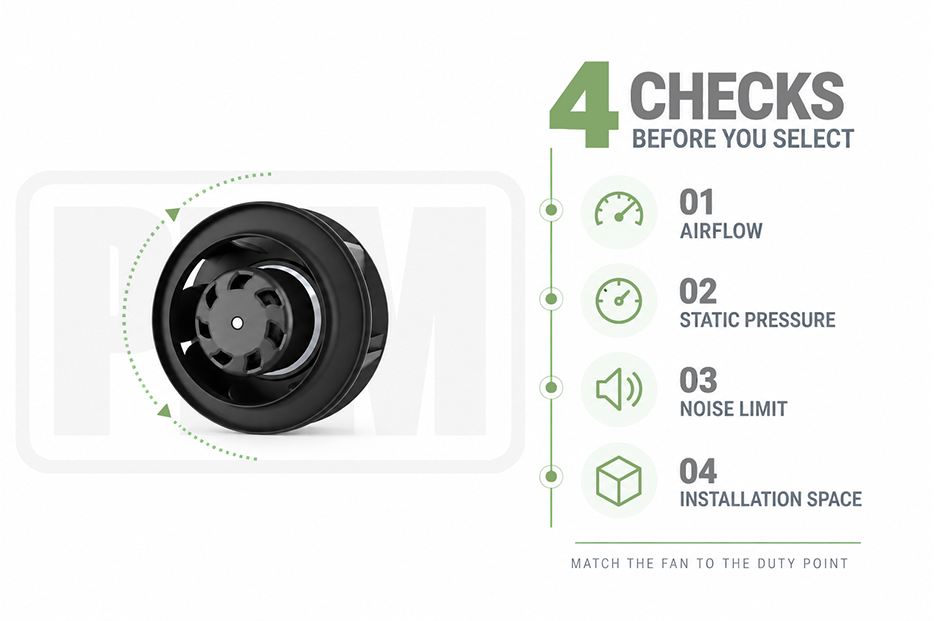
Axial and centrifugal EC fans can both appear in air-conditioning equipment, but they solve different airflow problems. The correct default depends on the resistance and geometry of the system.
|
EC fan type |
Best starting point |
Typical HVAC locations |
Main limitation |
|
Axial EC fan |
High airflow through a short, relatively open path |
Outdoor condensers, evaporators, heat exchangers, cooling towers |
Delivered airflow can fall quickly as system resistance increases |
|
Backward-curved centrifugal EC fan |
Medium- or high-pressure systems with coils, filters, or duct resistance |
AHUs, filtered ventilation units, precision cooling, heat-recovery systems |
Requires more careful inlet design and may need more installation volume |
|
Forward-curved centrifugal EC fan |
Compact equipment requiring moderate pressure and packaged airflow |
Fan-coil units, compact air-conditioning modules, smaller air handlers |
Operating range and power behavior must be checked against the fan curve |
|
EC duct fan |
Inline air movement in a defined duct branch |
Local ventilation, branch boosting, compact ducted systems |
Not a correction for an undersized or poorly designed duct network |
Choose an axial design when the HVAC duty requires high airflow and the air path is short and open. Condenser and evaporator applications are common examples. The axial format also offers shallow installation depth because air enters and leaves along the fan axis.
Check the pressure drop of the coil, guard, casing, and nearby structures. Recirculation around the coil or an obstruction close to the inlet can reduce capacity and increase sound. If pressure loss is high, a centrifugal construction may be the safer choice even when the required airflow is large.
A backward-curved centrifugal fan is a strong starting point when the fan must overcome filters, several coil rows, heat-recovery sections, or a duct system. These fans are used in air handlers and other pressure-dependent HVAC equipment because they can maintain airflow against greater resistance than a standard axial fan.
PBM's published backward-curved centrifugal fan range includes EC-AC options for different airflow and pressure duties. Final selection still requires the exact curve, input power, dimensions, and operating limits of the chosen model.
A forward-curved centrifugal fan can fit compact fan-coil units and packaged modules that need moderate pressure in limited space. Housing, inlet, and discharge geometry are part of the aerodynamic system, so the supplier should review the complete enclosure drawing.
Do not assume that a smaller fan at higher speed will be the quietest or most efficient choice. Compare candidate models at the required duty point and check motor loading across the full control range.
A catalog may list maximum airflow, maximum pressure, speed, power, and sound. These values may occur at different points and should not be treated as one simultaneous operating condition. The selected duty point should be located on the model's pressure-airflow curve at the intended speed.
Review at least four sets of data:
If the HVAC system has several modes, plot or check each expected point. Avoid unstable areas of the fan curve and confirm that the motor and electronics remain within their ratings at every commanded speed.
Two EC fans with similar aerodynamic performance may not be interchangeable. The supply, controller, signal logic, and fault behavior must fit the HVAC control architecture.
Specify the nominal voltage, phase, frequency, and allowable voltage range. Confirm maximum current, input power, grounding, connector or terminal arrangement, cable length, and any required power-factor correction. For export equipment, do not assume that one fan variant supports every regional supply.
Common control methods include 0–10 V, PWM, and digital communication, but availability varies by model. Define the controller output, signal reference, input impedance where relevant, minimum command, maximum command, stop behavior, and the expected response if the control wire is disconnected.
An HVAC controller may require a tachometer or frequency output, alarm contact, speed feedback, or an RS485 communication interface. Confirm the protocol and register definition rather than treating “RS485” as a complete specification. The control team should also define how the system reacts to blocked rotation, loss of feedback, overtemperature, or communication failure.
The usable speed range should match the HVAC load profile. Operating continuously at the bottom of an unsuitable range can result in inadequate airflow control, while selecting a fan that spends most of its life near maximum speed may leave no margin for filter loading or peak ambient conditions.
Fan noise depends on airflow, pressure, speed, blade design, inlet conditions, and the host equipment. Comparing one catalog dB value without the measurement method or operating point can lead to a poor decision.
Ask for sound data at or close to the intended duty point. State whether the project limits sound pressure or sound power and provide the measurement distance or applicable test requirement. In the equipment, also check:
Reducing speed can lower acoustic output, but only if the fan still meets airflow and pressure requirements. A larger fan running more slowly may be worth evaluating when space and cost permit.
Air-conditioning equipment may operate indoors, outdoors, in humid plant rooms, at low temperatures, or near salt and cleaning chemicals. State the minimum and maximum ambient and airstream temperatures, humidity, condensation, dust, water exposure, altitude, corrosion risk, and mounting orientation.
An IP rating describes tested protection against defined solid and water ingress. It does not by itself confirm resistance to salt, chemicals, UV exposure, continuous condensation, or an explosive atmosphere. If the fan is installed outdoors or in a wet section, review the exact enclosure, cable exit, connector, drainage, and mounting arrangement.
PBM offers IP55 axial fan options for projects requiring increased ingress protection. Suitability must be checked at model and installation level.
Fan ratings are measured under controlled test conditions. A production HVAC unit can impose non-uniform airflow, swirl, abrupt transitions, inlet blockage, and discharge restriction. These installation effects can lower airflow and raise power, noise, or vibration.
Send the supplier a drawing showing the fan, coil, filter, guard, cabinet walls, inlet, outlet, and nearest bend. Define:
A mechanically compatible fan can still perform badly if the inlet is blocked or the coil receives uneven airflow. Prototype testing should use the intended production geometry.
Purchase price is one part of an HVAC fan decision. A useful comparison includes input power across the expected operating schedule, controls, wiring, installation labor, acoustic treatment, maintenance access, replacement procedure, and downtime risk.
Do not apply a general energy-saving percentage to every EC fan conversion. Savings depend on the existing motor, fan type, duty cycle, pressure loss, control method, and operating point. Request comparable power data for the same airflow and pressure, then model annual consumption using the unit's real load profile.
For a retrofit, verify dimensions, electrical compatibility, sensor and controller behavior, airflow direction, and commissioning requirements. Replacing an AC fan with an EC model is not always a drop-in electrical change.
|
Selection item |
Information to provide |
What the supplier should return |
|
Application |
AHU, FCU, condenser, heat pump, precision AC, heat exchanger, or duct system |
Recommended fan construction and reason |
|
Duty point |
Airflow and total static pressure for each operating mode |
Fan curve with proposed operating points marked |
|
Electrical |
Voltage, phase, frequency, current limit, connector |
Electrical data and wiring diagram |
|
Controls |
0–10 V, PWM, communication, feedback, alarm logic |
Control specification and signal behavior |
|
Environment |
Temperature, humidity, dust, water, corrosion, altitude |
Permitted conditions and protection rating |
|
Mechanical |
Drawing, space limit, mounting, guard, cable exit |
Dimensioned drawing and installation requirements |
|
Acoustics |
Sound target and measurement basis |
Sound data at or near the duty point |
|
Project |
Sample quantity, annual demand, validation date, production schedule |
Sample plan, quotation scope, and proposed delivery schedule |
PBM supplies EC motorized fan options for air-conditioning and HVAC applications, including fan-coil units, air-handling units, condensers, heat pumps, heat exchangers, and precision cooling equipment. Its product families include axial fans, backward- and forward-curved centrifugal fans, single- and dual-inlet blowers, and duct fans.
The broad product range is useful only when it is narrowed by the application. A PBM model recommendation should be based on the customer's required airflow and pressure, electrical supply, control method, environment, mechanical drawing, and acoustic limit. Published category maximums are screening data; the current model datasheet and fan curve should control final selection.
An axial EC fan is a common starting point because a condenser needs high airflow through a relatively short path. Confirm the coil pressure drop, inlet and outlet clearance, ambient temperature, recirculation risk, and airflow at the required pressure.
A backward-curved centrifugal EC fan is often the stronger starting point when the AHU includes filters, multiple coil rows, heat recovery, or duct resistance. Select it from the complete system duty point rather than from the fan diameter.
It can suit compact FCUs that need moderate pressure and packaged airflow. Check the housing, inlet, discharge, available depth, motor loading, control range, and sound at the required operating points.
No. Maximum airflow is commonly close to free delivery. The selected fan must provide the required airflow against the total static pressure of the installed HVAC system.
An EC-AC fan accepts an AC supply and contains electronics that rectify and control power for the brushless motor. An EC-DC or DC brushless fan uses a DC supply from the host equipment. Confirm the exact electrical architecture and terminology with the supplier.
No fixed saving applies to every project. EC speed control can reduce energy use in variable-load operation, but the result depends on fan selection, system resistance, duty cycle, control logic, and the equipment being replaced.
Use the signal supported by both the HVAC controller and the selected fan. Define the complete interface for 0–10 V, PWM, or digital communication, including stop behavior, feedback, alarms, and loss-of-signal response.
Compare sound data at the same airflow and static pressure using the same measurement basis. Also test the fan in the complete cabinet because coils, guards, panels, and inlet geometry can change the acoustic result.
Send the HVAC application, airflow and pressure points, voltage, control signal, temperature and humidity range, ingress or corrosion requirements, dimensional drawing, noise target, quantity, validation schedule, and production timeline.
The right EC fan for an air-conditioning or HVAC system is the fan that meets every required operating point inside the actual equipment. Start with airflow and total static pressure, choose the correct axial or centrifugal construction, then verify the electrical interface, control range, sound, environment, and installation geometry.
To request a PBM model review, submit the application, duty points, voltage, control method, environmental conditions, installation drawing, acoustic limit, quantity, and project schedule through the contact page. The next step should be a curve-based recommendation followed by sample testing in the production-representative HVAC assembly.
 If you have any interest in our products,please feel free to contact us & we are ready to serve you

By continuing to use the site you agree to our privacy policy Terms and Conditions.